Volt meter
Introduction
Nowadays Voltmeters are commonly using devices like in the digital voltmeter or multi meter or solar panel power monitoring system anyway do you know how it is working here I’m trying to understanding that how it is working Here I’m creating an Arduino based voltmeter so we need to understand Arduino a little bit before getting into that take a look at this Arduino example program called ReadAnalogVoltage our base program is this, by modifying the program and the hardware we can measure a wide range of voltages.
ANALOG PIN & ITS THEORY
First, we have to take a look at the Arduino pins here we are using the Analog pins to measure the voltage and it is a 10 bit ADC (Analog to Digital Converter) so it can chop or sampling the input signal = Input signal/210 but Arduino can only handle the voltage 0 to up to +5V if the voltage exceeds it will probably burn the entire Arduino or the pins so be careful with this voltage,
so if we take the maximum voltage such as +5V then the ADC will chop or sampling value is
\[1 value = 5/210 = 0.00488 ~4.9mV\] \[1023 value = (5/210 )*1023 =5V\]OR Don’t worry, Simply I will explain that here
\[0 Volts = 0 Value\] \[5 Volts = 1023 Values (210=1023)\] \[1 Volts =1023/5 =204.6 values\] \[2.5 Volts = (1023/5)*2.5 = 511.5 values\] \[5 Volts = (1023/5)*5 = 1023 values\]OK I know it’s somewhat boring so let’s jump to our hardware designing part
VOLTAGE DIVIDER
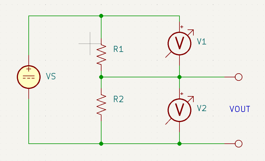
In electronics, the voltage divider rule is a simple and most important electronic circuit, which is used to change a large voltage into a small voltage. Using just an i/p voltage and two series resistors we can get an o/p voltage. Here, the output voltage is a fraction of the i/p voltage. The best example of the voltage divider is two resistors are connected in series. When the i/p voltage is applied across the pair of the resistor and the o/p voltage will appear from the connection between them. Generally, these dividers are used to reduce the magnitude of the voltage or to create reference voltage and also used at low frequencies as a signal attenuator.
 Voltage divider
Simply voltage divider circuit is a very common circuit that takes a higher voltage and converts it to a lower one by using a pair of resistors. The formula for calculating the output voltage is based on Ohms Law and is shown below.
\[VOUT = {VS * R2 \over (R1+R2)}\]DERIVATION
\[V1 = IR1\] \[V2=IR2\] \[VS = IR1+IR2\] \[VS = I(R1+R2)\] \[I = {VS \over R1+R2}\] \[V2 = IR2\] \[V2 = ({VS \over R1+R2})*R2\] \[VOUT=({VS \over R1+R2})*R2\]You can use this calculator to calculate Vout voltage😁
Voltage Divider Calculator:
OK let’s end this I think we can jump to the action😃
ARDUINO VOLTMETER
Here we are using an Arduino as a voltmeter I’ll give the circuit diagram and the code.
This for the Arduino interfaced with 4bit mode LCD..
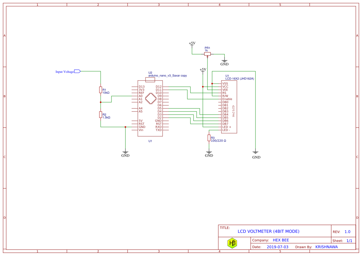 Arduino Voltage divider
Project repo Available here.
It can measure up to 40 Volts!