BEEIRON

Project repo Available here.
Story
In the past few years, I had been using a Solderon 25W/230V soldering iron for all my soldering work. However, I decided to upgrade to a temperature-controlled soldering iron. While searching for a good temperature-controlled soldering iron, I had the idea of making one myself.
I began browsing the internet and came across the JBC brand, which had a nice selection of soldering irons. Eventually, I purchased a JBC handle that is compatible with JBC T245 cartridges.
It turned out that the process was not as easy as I initially thought. I encountered numerous challenges along the way, especially considering that this particular version, v0.0.4, is still in beta and not ready for production. In this blog, I will outline the challenges I faced, the mistakes I made, and discuss the issues with the previous version as well as the present one. Additionally, I will address the changes that need to be made in the next revision.
1. Features and specification
- Using T245 General Purpose Handle.
- Using C245938 - Spoon Cartridge Ø 3.8
- Achieve Room temp - 300 °C in 2 Seconds!
- The soldering station has a 0.96’ OLED display.
- For setting/adjusting the temperature it has a pot.
- It has capability of the live power measurement.
- Replace default connector of JBC 245 with GX-16 5 Pin connector
2. Simplified block diagram

 Power path of BEEIRON I have a setup with a toroidal transformer that has two secondary windings. One winding provides a 12-0-12V output, which I use for my board supply. To convert the AC voltage to DC, I’ve used a bridge rectifier and filter capacitor.
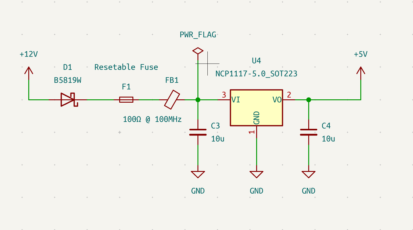
In order to power my MCU and peripherals at different levels, I’ve incorporated Low Dropout Regulators (LDOs). The first LDO generates a 3.3V output specifically for the Thermocouple to Digital converter IC (MAX31856) and the level shifter circuit. The second LDO produces a 5V output, which primarily powers the MCU and other peripherals on the board.
Additionally, I have another winding with a 24-0-24V output. I utilize only the 24-0V portion to supply power to the heating element of the JBC T245 Cartridge.
Overall, this setup provides the necessary voltage levels for each component, ensuring efficient operation.
 Block diagram of BEEIRON
The diagram is quite straightforward and has a simple design. Let’s begin by discussing the user interface section. The I2C-based OLED display is used to show both the set temperature and the real-time temperature. It provides a clear and easy-to-read interface.
For temperature adjustment, we have a minimalistic setup using a Potentiometer (POT). It allows precise control over the set temperature and real-time temperature adjustments.
The pushbutton, accompanied by an LED, serves the purpose of confirming the set temperature. The LED acts as an indicator for the real-time iron supply voltage.
Moving on to the power electronics section! Here, a 24VAC power supply is utilized to operate the heating element. A TRIAC-based switch is placed between the supply and heating element to regulate the voltage and achieve the desired temperature.
To maintain the tip temperature, a thermocouple is employed as a closed-loop feedback system. Additionally, a hall effect-based current sensor is used to measure the current drawn by the heating element, although it was not implemented in this setup. It is an optional feature that could be considered for future improvements.
You might be wondering about the purpose of the optocoupler. Well, here’s the answer. The 24VAC supply is also connected to a bridge rectifier, which converts the AC cycle into a rippled DC waveform. The optocoupler’s LED is triggered when the rippled DC voltage exceeds the LED’s dropout voltage. When the LED is illuminated, the optocoupler’s transistor conducts, resulting in a LOW voltage (0V) at the controller side. Conversely, when the DC ripple voltage drops below the LED’s dropout voltage, the LED turns off, causing the optocoupler transistor to stop conducting. This action produces a HIGH voltage (5V) pulse with the assistance of a pull-up resistor at the controller side. This pulse serves as an interrupt signal.
Using this interrupt signal and a specific code logic, I devised the following procedure:
- The TRIAC turns on once the set temperature is confirmed.
- After counting 6 interrupt signals, the TRIAC’s conduction is halted on the 7th interrupt signal.
- The temperature is measured, and the interrupt counter is reset to 0.
- If the temperature hasn’t reached the set temperature, the above process repeats.
- Once the temperature is reached or surpassed, the TRIAC turns off and the interrupt counter resets. The procedure then restarts from the second step.
We really don’t need a optocoupler based TRIAC ON/OFF system. why we are using this system is to
- avoid phase cutting
- Zero cross phase cutting to reduce the humming noise
- Avoid RFI
- Avoid Humming noise
That covers all the details of the block diagram.
3. Components
3.1 JBC T245 Spoon Cartridge Ø 3.8
_Completa.gif) C245938 Spoon Cartridge Ø 3.8
C245938 Spoon Cartridge Ø 3.8
The JBC T245 Spoon Cartridge Ø 3.8 is a soldering iron cartridge designed for use with JBC soldering stations. Here are the specifications for this specific cartridge
| Attribute | Details |
|---|---|
| Cartridge Type | T245 Spoon Cartridge |
| Cartridge Diameter | 3.8 mm |
| Weight | 7 gr (0.02 lb) |
| Dimension | 110 x 12 x 12 mm |
| Resistance | 1-3Ω |
| Thermocouple | N Type (Probably) |
- JBC soldering stations that support the T245 series cartridges
- It contains a heating element at the top of its tip that rapidly heats up to the desired temperature.
- The temperature range may vary based on the specific soldering station, but typically JBC cartridges can reach temperatures up to 450°C (842°F).
- The spoon cartridge is commonly used for precise soldering tasks that require the transfer and application of small amounts of solder or for working with components that require careful soldering techniques.
- JBC cartridges are known for their long lifespan and durability due to the use of high-quality materials and advanced manufacturing processes.
Please add the info about handle also…
 Internal structure of JBC T245 Tip
Just a heads up, this diagram illustrates the internal structure of a typical JBC T245 Tip. I’m amazed by how they manufactured this tip; it’s truly an engineering marvel. Essentially, it consists of two metal tubes. The inner tube is called the Common (C3), while the next layer is covered with an insulator, and the outer layer is the second tube, known as the Heater (C2). At the top of the tip, there’s a spiral heater configuration, as depicted in the picture.
What’s intriguing is the placement of the thermocouple. Rather than providing separate pins for the heating element and the thermocouple, they combined one of the thermocouple pins with the heating element pin into a single pin. To make it easier to understand, I’ve included a schematic configuration of the tip. Hopefully, combining these pins is a simple task during manufacturing. As you can see from the picture, the Thermocouple (C1) is also a part of the Common (C3). The thermocouple is formed by the intersection of both metals. I believe they used a different metal fused at the intersection of these metals to create the thermocouple. It’s quite fascinating, isn’t it?
If you’d like to learn more about thermocouples, you can click here.
Additionally, from my investigation, I’ve determined that it’s an N-type thermocouple, if I’m not mistaken. To test the thermocouple, I used boiling water as a reference temperature (100°C) and measured the voltage across it. I obtained a reading of approximately 2.7mV. I used my Mini Hotplate MHP30 to measure various temperatures and recorded the voltage readings. Although I can’t guarantee the accuracy of my data, I have confidence in my findings. Based on the data, I concluded that the thermocouple is likely N-type. I cross-checked my readings using a thermocouple chart.
Here is the thermocouple chart click here
3.2 ATMEGA328
 8-bit Microcontrollers - MCU 32KB In-system Flash 20MHz 1.8V-5.5V
Specification
| Attributes | Description |
|---|---|
| Program Memory Type | Flash |
| Program Memory Size (KB) | 32 |
| CPU Speed (MIPS/DMIPS) | 20 |
| Data EEPROM (bytes) | 1024 |
| Timers | 2 x 8-bit 1 x 16-bit |
| Stand alone PWM | 6 |
| ADC Channels | 8 |
| Max ADC Resolution (bits) | 10 |
| Number of Comparators | 1 |
| Temp. Range Min. | -40 |
| Temp. Range Max. | 85 |
| Operation Voltage Max.(V) | 5.5 |
| Operation Voltage Min.(V) | 1.8 |
| Pin Count | 32 |
| Low Power | Yes |
| I2C | 1 |
| SPI | 1 |
Why Atmega328?
At the time of this project I was very comfortable with Arduino platform so I decided to use the Atmega328. Since it doesn’t have any complicated toolchain setup it’s really easy to work with Arduino IDE also it have many resources and supports are available
While doing this project I created a pinout document for ATMEGA328, If you are interested check below.
Atmega328 pinout available here.
3.3 Toroidal Transformer
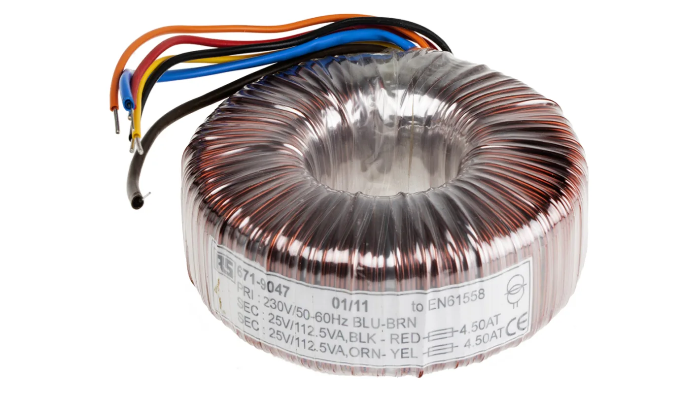 Toroidal transformer
Here, I am using a toroidal transformer that has two center-tapped secondary windings. One of the windings provides 12-0-12V, and the other winding provides 24-0-24V.
In the power path diagram, you can see that the 12-0V output is used for the board supply, while the 24-0V output is used for the soldering iron supply.
Specification
| Attributes | Description |
|---|---|
| Primary Winding voltage | 230VAC |
| Frequency | 50Hz |
| Secondary Winding Voltage 1 | 12-0-12VAC |
| Secondary Winding Voltage 2 | 24-0-24VAC |
| Dimension | Height x Width |
| Weight | in kg |
Why Toroidal Transformer?
Compact Size: Toroidal transformers are more compact and lighter than conventional transformers with the same power rating. The toroidal shape allows for efficient use of space, making them ideal for applications where size and weight are critical factors.
High Efficiency: Toroidal transformers are known for their high efficiency. The toroidal core design minimizes magnetic flux leakage and provides a more direct magnetic path, resulting in lower losses and improved overall efficiency.
Low Electromagnetic Interference (EMI): Toroidal transformers produce less electromagnetic interference compared to laminated transformers. The toroidal core design reduces the magnetic field radiation and minimizes EMI, making them suitable for use in sensitive electronic devices.
Reduced Mechanical Hum: Toroidal transformers produce less audible noise or mechanical hum compared to traditional transformers. The tightly wound toroidal core design reduces vibrations and eliminates the buzzing sound often associated with laminated transformers.
Better Voltage Regulation: The circular design of the toroidal core allows for a more uniform distribution of the windings, resulting in better voltage regulation. Toroidal transformers can provide stable output voltage even under varying load conditions.
Higher Power Density: Due to their compact size and efficient design, toroidal transformers can achieve higher power densities. This makes them suitable for applications where space is limited, such as in audio equipment, medical devices, or power supplies.
Improved Thermal Performance: The toroidal shape provides a larger surface area for heat dissipation compared to traditional transformers. This allows for better cooling and thermal management, ensuring the transformer operates within acceptable temperature limits.
Easier Mounting: Toroidal transformers often have a center hole, which facilitates easy mounting and installation. The central hole allows for secure and convenient mounting using screws or bolts, simplifying the integration process.
3.4 MAX31856
 MAX31856
The MAX31856 is the IC which convert the wide range of thermocouple to digital data through SPI bus. thermocouple inputs are protected against overvoltage conditions up to ±45V.
Specification
| Attributes | Description |
|---|---|
| Voltage | 3.3V |
| ADC(bits) | 19bits |
| Support thermocouple | K, J, N, R, S, T, E, & B |
| Protocol | SPI |
3.5 OLED 0.96’Display
I used a 0.96” OLED display to show the set temperature and real-time temperature. It’s a minimalistic setup, but it serves the purpose effectively. 😼
Specification
| Attributes | Description |
|---|---|
| Voltage | 3.3V |
| Pixel Resolution | 128 x 64 |
| Protocol | I2C |
| Module Dimension | 27.3027.302.37 |
3.6 Potentiometer
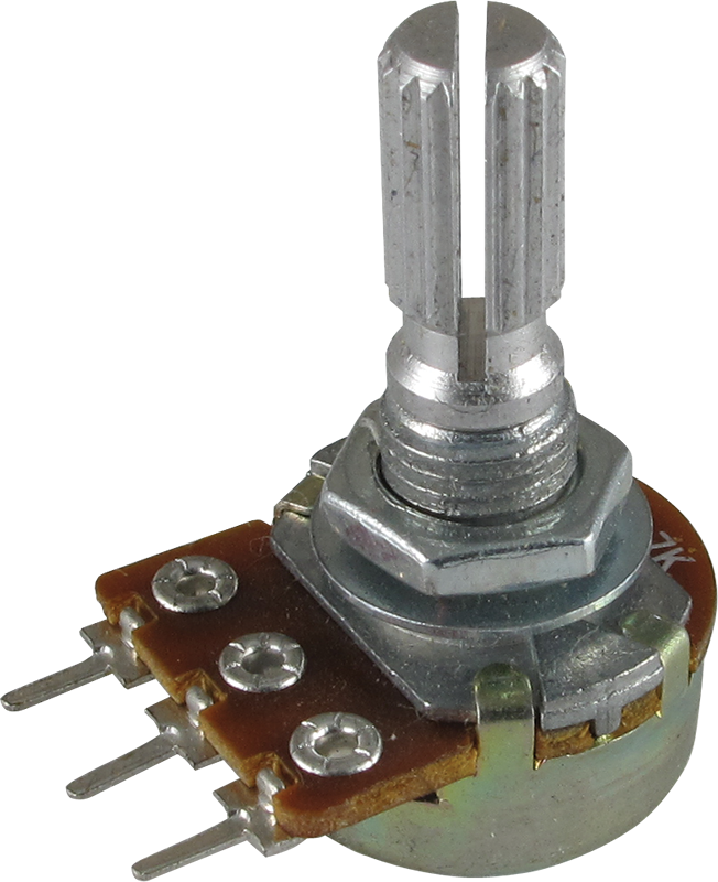 potentiometer At first, I contemplated using a rotary encoder to navigate the menu. However, in the interest of simplicity, I chose to use a potentiometer instead to adjust the set temperature. Additionally, I incorporated a simple pushbutton for selecting the desired temperature. This configuration provides a straightforward and user-friendly interface.
Specification
| Attributes | Description |
|---|---|
| Resistance | 0-10KΩ |
3.7 Pushbutton & LED
 Pushbutton with LED
In my setup, I have incorporated a pushbutton along with an LED. The main purpose of the pushbutton is to turn on the soldering iron at the desired temperature and turn it off by pressing the button again. On the other hand, the LED serves a single function, which is to indicate the status of the iron supply while it is turned on.
3.8 Opto-coupler
 4N25
4N25
I’m using a widely-used optocoupler called the 4N25, which combines an infrared LED and a phototransistor. It’s a generic component that provides electrical isolation between circuits by transmitting signals through light.
Specification
| Attributes | Description |
|---|---|
| LED Forward voltage | 1.18v |
| LED Forward Current | 10mA |
3.9 TRIAC and TRIAC coupler
I used the combo of BTB26-600 as the TRIAC and the MOC3020M as the TRIAC coupler. In this setup, the MCU controls the TRIAC coupler, which then triggers the TRIAC. By using a coupler, we provide isolation to the circuit, which is a good practice. TRIACs and DIACs are fascinating devices, and they could be a topic for another blog!
Specification of TRIAC BTB26-600

| Attributes | Description |
|---|---|
| IT(RMS) | 25A |
| VDRM/VRRM | 600V to 800V |
| IGT(Standard) | 50mA |
| IGT(Snubberless) | 35/50mA |
The MOC301XM and MOC302XM series are optically isolated TRIAC driver devices. They consist of a GaAs infrared emitting diode and a light-activated silicon bilateral switch that acts like a TRIAC. These devices are specifically designed for interfacing electronic controls with power TRIACs to control resistive and inductive loads in 115 VAC operations. It’s important to note that this TRIAC coupler is a random phase trigger, rather than a zero-cross phase trigger.
Specification of MOC3020M

| Attributes | Description |
|---|---|
| Off−State Output Terminal Voltage | 400V |
| Peak Repetitive Surge Current | 1A |
| LED forward current | 30mA |
| Input Forward Voltage | 1.15V |
4. Schematic
Project Schematic Available here.
Power supply
Bridge Rectifier
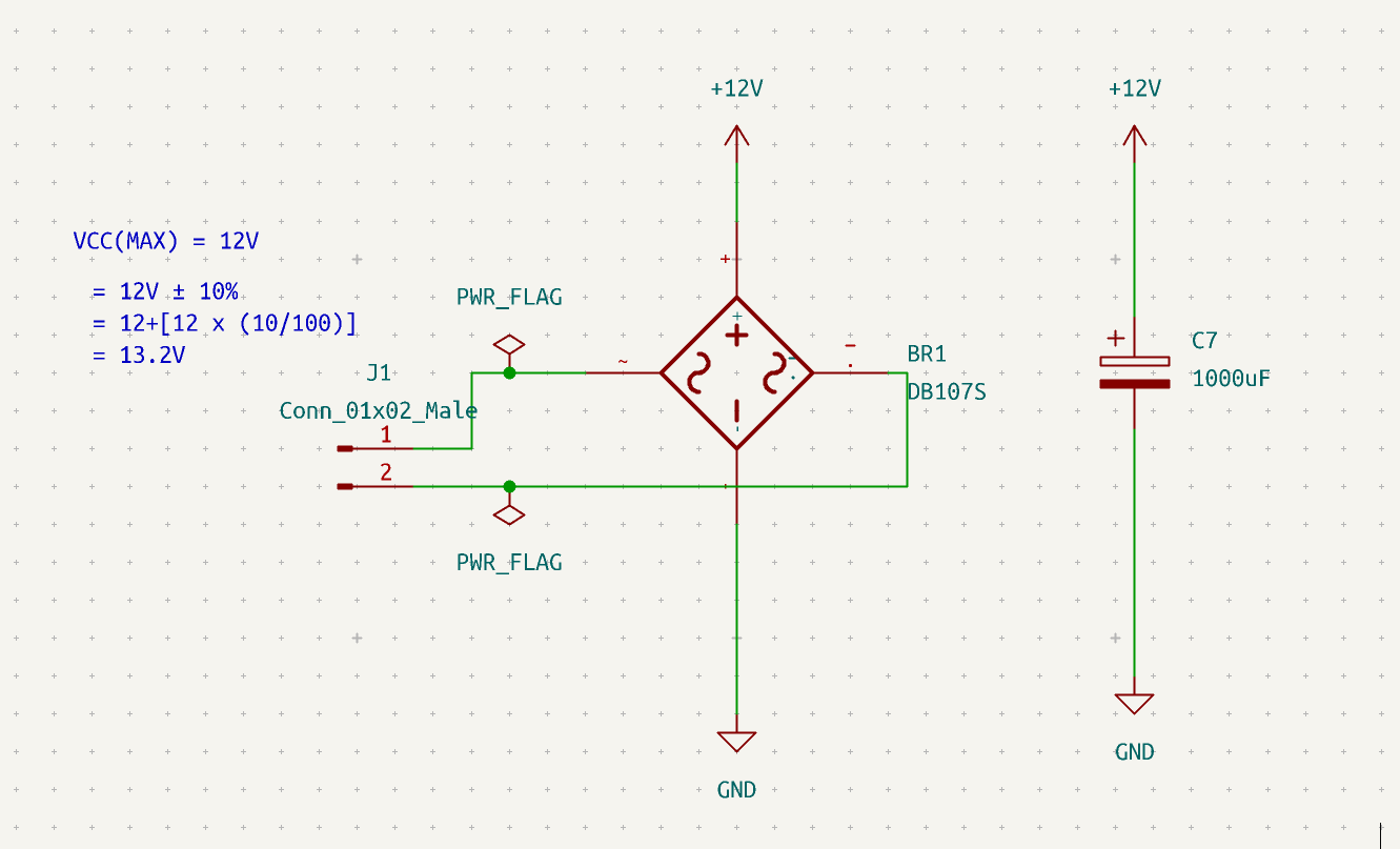
maximum and minimum voltage for a 12V AC power supply with a tolerance of +/-10%.
Maximum voltage: 12V + 10% = 12V + (0.10 * 12V) = 12V + 1.2V = 13.2V
Minimum voltage: 12V - 10% = 12V - (0.10 * 12V) = 12V - 1.2V = 10.8V
Now, let’s calculate the output voltage of a bridge rectifier using the maximum voltage of 13.2V. A bridge rectifier converts AC voltage to DC voltage with voltage drops of two diodes.
Voltage drop of a diode = ~0.7V Then, for 2 diodes its 2 x 0.7V = 1.4V
The output voltage of the bridge rectifier = 13.2V - 1.4V = 11.8V
Finding the ripple voltage of a 1000uF capacitor
Cap equation:
\[i = {C} {dv\over dt}\]If the current is constant, and Δv is Vripple:
\[I = C{Δv \over Δt}\]For a full-wave rectifier(2 x f):
\[Δt = {1 \over 2f}\]Combining equations and solving:
\[I = C{Δv2f}\]Then we can find the equation for Δv,
\[Δv = {I \over C2f}\]Where: Δv is the ripple voltage, I is the load current, f is the frequency of the AC input, and C is the capacitance.
Let’s assume a load current of 0.5A, a frequency of 50Hz, and a capacitance of 1000μF (0.001F). Using these values, we can calculate the ripple voltage.
Vripple = (0.5A) / (2 * 50Hz * 0.001F) ≈ 4.16V
Therefore, the ripple voltage in the rectifier circuit with a 1000μF capacitor, assuming a load current of 0.5A and a 50Hz AC input, is approximately 4.16V.
 exp diode fuse and Ferrite beads also reg caps calculations-> max ip voltage of reg reg pwr dissipation
 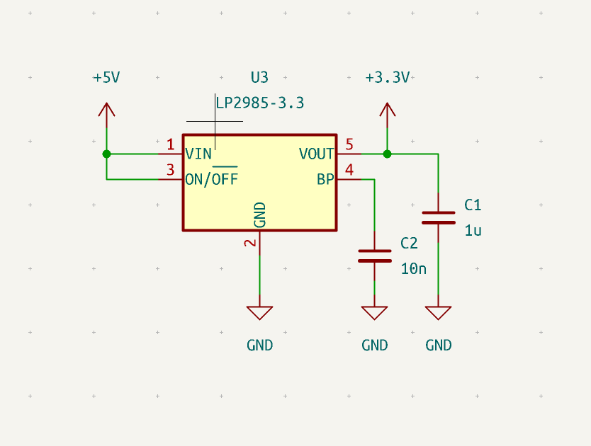 calculations-> max ip voltage of reg reg pwr dissipation
Why this kolaveri?
5. Code
1
2
3
4
5
6
7
8
9
10
11
12
13
14
15
16
17
18
19
20
21
22
23
24
25
26
27
28
29
30
31
32
33
34
35
36
37
38
39
40
41
42
43
44
45
46
47
48
49
50
51
52
53
54
55
56
57
58
59
60
61
62
63
64
65
66
67
68
69
70
71
72
73
74
75
76
77
78
79
80
81
82
83
84
85
86
87
88
89
90
91
92
93
94
95
96
97
98
99
100
101
102
103
104
105
106
107
108
109
110
111
112
113
114
115
116
117
118
119
120
121
122
123
124
125
126
127
128
129
130
131
132
133
134
135
136
137
138
139
140
141
142
143
144
145
146
147
148
149
150
151
152
153
154
155
156
157
158
159
160
// This example demonstrates continuous conversion mode using the
// DRDY pin to check for conversion completion.
#include <Wire.h>
#include <Adafruit_GFX.h>
#include <Adafruit_SSD1306.h>
#include <Adafruit_MAX31856.h>
const int triac = 8;
const int interruptPin = 2;
int set = 200;
int counter;
float temperature = 0;
#define DRDY_PIN 7
#define SCREEN_WIDTH 128 // OLED display width, in pixels
#define SCREEN_HEIGHT 32 // OLED display height, in pixels
#define potentiometer A1
int pottemperature;
#define button 4
#define led 9
bool state = 0;
const float mov_avg_alpha = 0.1;
static float mov_avg = -100;
double value;
// Declaration for an SSD1306 display connected to I2C (SDA, SCL pins)
Adafruit_SSD1306 display(SCREEN_WIDTH, SCREEN_HEIGHT, &Wire, -1);

// Use software SPI: CS, DI, DO, CLK
//Adafruit_MAX31856 maxthermo = Adafruit_MAX31856(10, 11, 12, 13);
// use hardware SPI, just pass in the CS pin
Adafruit_MAX31856 maxthermo = Adafruit_MAX31856(10);

void setup() {
  pinMode(button, INPUT_PULLUP);
  pinMode(led, OUTPUT);
  delay(1000);
 // Serial.begin(115200);
  if (!display.begin(SSD1306_SWITCHCAPVCC, 0x3C)) { // Address 0x3D for 128x64
    //    Serial.println(F("SSD1306 allocation failed"));
    for (;;);
  }
  while (!Serial) delay(10);
  //Serial.println("MAX31856 thermocouple test");

  pinMode(DRDY_PIN, INPUT);

  if (!maxthermo.begin()) {
    //    Serial.println("Could not initialize thermocouple.");
    while (1) delay(10);
  }

  maxthermo.setThermocoupleType(MAX31856_TCTYPE_K);

  //  Serial.print("Thermocouple type: ");
  switch (maxthermo.getThermocoupleType() ) {
    case MAX31856_TCTYPE_B: /*Serial.println("B Type");*/ break;
    case MAX31856_TCTYPE_E: /*Serial.println("E Type");*/ break;
    case MAX31856_TCTYPE_J: /*Serial.println("J Type");*/ break;
    case MAX31856_TCTYPE_K: /*Serial.println("K Type");*/ break;
    case MAX31856_TCTYPE_N: /*Serial.println("N Type");*/ break;
    case MAX31856_TCTYPE_R: /*Serial.println("R Type");*/ break;
    case MAX31856_TCTYPE_S: /*Serial.println("S Type");*/ break;
    case MAX31856_TCTYPE_T: /*Serial.println("T Type");*/ break;
    case MAX31856_VMODE_G8: /*Serial.println("Voltage x8 Gain mode");*/ break;
    case MAX31856_VMODE_G32: /*Serial.println("Voltage x8 Gain mode");*/ break;
    default: /*Serial.println("Unknown");*/ break;
  }
  pinMode(triac, OUTPUT);
  attachInterrupt(digitalPinToInterrupt(interruptPin), zero, FALLING);
  maxthermo.setConversionMode(MAX31856_CONTINUOUS);
  //  maxthermo.setConversionMode(MAX31856_ONESHOT_NOWAIT);
}
void zero() {
  counter++;
  //Serial.println(counter);
  if (counter < 60) {
    if (round(mov_avg) <= pottemperature) {
      digitalWrite(triac, HIGH);
    }
    else {
      digitalWrite(triac, LOW);
    }
  }
  if (counter == 60) {
    digitalWrite(triac, LOW);

    detachInterrupt(0);
    int count = 0;
    while (digitalRead(DRDY_PIN)) {
      if (count++ > 100) {
        count = 0;
        //Serial.println(count);
      }
    }
    //    maxthermo.triggerOneShot();
    //    if (maxthermo.conversionComplete()) {
    //      //Serial.println(maxthermo.readThermocoupleTemperature());
    //      temperature = maxthermo.readThermocoupleTemperature();
    //    } else {
    //      Serial.println("Conversion not complete!");
    //    }
    temperature = maxthermo.readThermocoupleTemperature();
    //Serial.println(maxthermo.readThermocoupleTemperature());
    counter = 0;
    attachInterrupt(0, zero, FALLING);
  }
}
void loop() {
  Serial.print(pottemperature);
  Serial.print("\t");
  Serial.print(round(mov_avg));
  Serial.println();

   value = maxthermo.readThermocoupleTemperature();
  if (mov_avg == -100)
    mov_avg = value;
  mov_avg = mov_avg_alpha * value + (1 - mov_avg_alpha) * mov_avg;
  //  Serial.print(value);
  //  Serial.print("\t");
  //  Serial.print(round(value));
  //  Serial.print("\t");
  //  Serial.print(mov_avg);
  //  Serial.print("\t");
  //  Serial.print(round(mov_avg));
  //  Serial.println();
  if (digitalRead(button) == 0) {
    state = ! state;
    delay(500);
  }

  digitalWrite(led, !state);
  if (state == true) {
    updateDisplay();
  }
  else {
    display.clearDisplay();
    display.setTextSize(2);
    display.setTextColor(WHITE);
    display.setCursor(8, 10);
    // Display static text
    display.print("POWER OFF!");
    display.display();
  }

  }
  void updateDisplay() {
    pottemperature = analogRead(round(potentiometer));
    pottemperature = map(pottemperature, 0, 1023, 0, 300);
    display.clearDisplay();
    display.setTextSize(2);
    display.setTextColor(WHITE);
    display.setCursor(0, 0);
    // Display static text
    display.print("SET:");
    display.print(pottemperature);
    display.setCursor(0, 19);
    display.print("TMP:");
    display.println(value);
//    display.println(round(mov_avg));
    display.display();

  }
8. Reference
https://www.eevblog.com/forum/testgear/jbc-soldering-station-cd-2bc-complete-schematic-analysis/