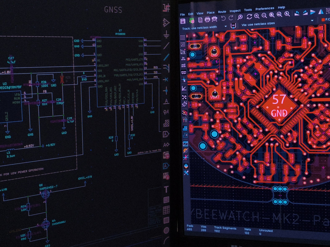
BEEWATCH-MK2 Part 2 -Schematic
Introduction
Here, I’m explaining the complete architecture of the BEEWATCH MK2, describing each block and how and why I designed the circuits. I hope you enjoy the process! I’ll walk you through all the steps, so sit back, relax, and enjoy my blog. If you have any questions or suggestions, please feel free to comment below.
BLOCK DIAGRAMS
Before understanding the schematic, it is always better to create a block diagram that conveys exactly what is in the system. Here, I have made two block diagrams:
- Power Architecture Block Diagram
- Functional Block Diagram
The Power Architecture Block Diagram shows how power is distributed to each peripheral/block, including the voltage and current consumption details. This makes it easier to understand the overall power flow and power consumption of the device I am designing.
On the other hand, the Functional Block Diagram provides details on how the peripherals/blocks are connected to each other and to the controller. This gives an idea of how the actual hardware will work, including the interfaces used and the connections between each block/peripheral.
BEEWATCH MK2 Power Architecture Block diagram
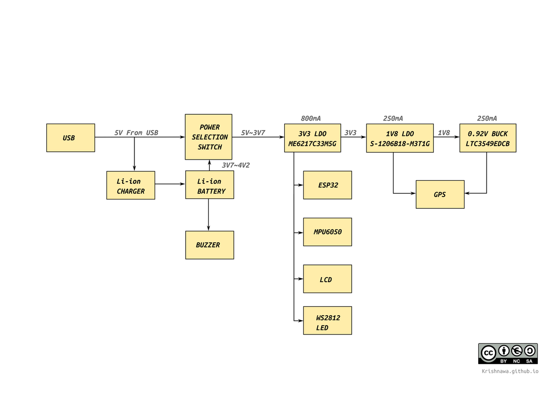 BEEWATCH MK2 Power Architecture
Basically, it’s a watch, so the power source is a 3.7V Li-ion battery with a capacity of 250mAh. To charge this battery, I used a Li-ion charger block. I used a USB Type-C connector for both charging and programming the device.
The buzzer is powered directly from the battery. The controller (ESP32), gyroscope sensor (MPU6050), LCD screen, and an optional RGB LED (WS2812) are all powered from a 3.3V regulator (ME6217C33M5G) with a maximum current limit of 800mA.
For the GPS module, two voltage levels are required: a 1.8V LDO (S-1206B18-M3T1G) and a 0.92V buck converter (LTC3549EDCB). Both the 1.8V LDO and 0.92V buck can handle up to 250mA of current.
BEEWATCH MK2 Functional block diagram
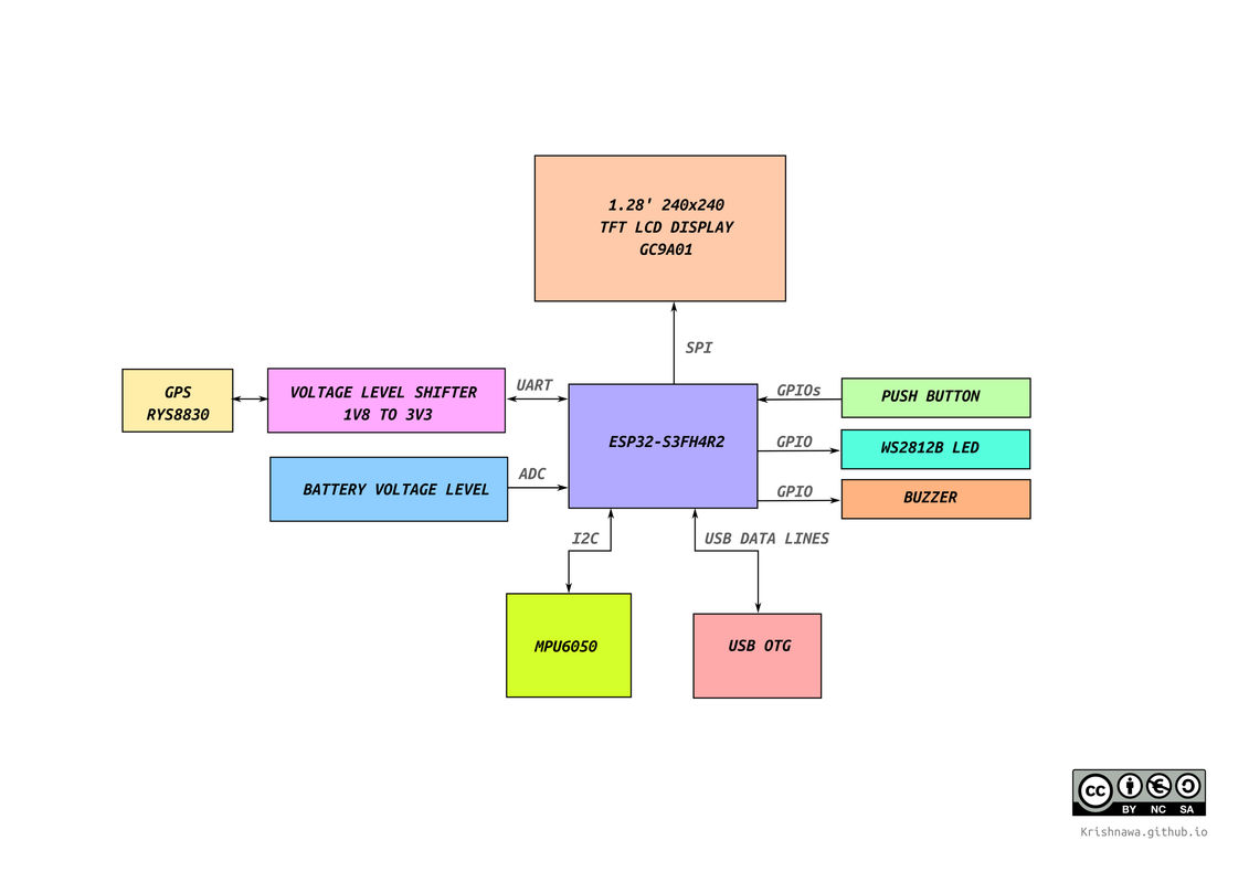 BEEWATCH MK2 Functional block diagram
As you can see, it’s a fairly simple watch, so there aren’t a large number of peripherals.
The main component is the display, which is a 1.28” 240×240 TFT LCD with the GC9A01 driver. This display is connected through the SPI interface.
Another key component is the GPS module from Reyax (RYS8830). It supports both I2C and UART interfaces, but I used UART to keep things simple. Additionally, a voltage level shifter circuit is required to connect it to the ESP32’s UART, since the GPS operates at 1.8V and the ESP32 also works at 1.8V.
I’m using the MPU6050 to get gyroscope information, which communicates via the I2C interface. To measure the battery voltage, I’m using one ADC pin. For programming and debugging, I’m using a USB Type-C connection, as the ESP32-S3 has a USB OTG interface.
For the two push buttons, WS2812B LED, and buzzer, I’m using GPIO pins.