EMI/EMC Testing with GTEM Cell for Pre Compliance

Why we are doing Electromagnetic Interference (EMI) and Electromagnetic Compatibility (EMC) testing?
Electromagnetic Interference (EMI) and Electromagnetic Compatibility (EMC) testing are done to make sure electronic devices, like phones or computers, work properly and don’t mess with other devices.
Stop Devices from Causing Trouble (EMI): EMI testing checks if a device gives off unwanted signals that could mess up things like radios, TVs, or medical equipment. The FCC (a U.S. regulator) has rules to keep these signals low so everything works smoothly.
Make Sure Devices Can Handle Interference (EMC): EMC testing makes sure a device can still work when it’s around other signals, like from cell towers or power lines. It’s like checking if your phone still works near a strong Wi-Fi signal.
Follow the Rules: The FCC requires these tests for devices sold in the U.S. If a device fails, it can’t be sold, and the maker could get in trouble.
Keep Things Safe and Reliable: Testing prevents devices from failing in ways that could be dangerous (like in medical or car equipment) and ensures they work as promised.
Get Products to Market: Passing these tests is like getting a “stamp of approval” to sell your device in the U.S.
EMI/EMC Standards
Here are the most widely used families of standards:
FCC (U.S.A)
Title 47 CFR Part 15 (Subparts B, C, E)
- Regulates EMI emissions for digital devices.
- Class A: Commercial/industrial equipment (less strict).
- Class B: Residential equipment (more strict).
- Radiated & conducted emissions are covered.
- Example: FCC Part 15 Subpart B (Unintentional Radiators).
CISPR / IEC (International)
Developed by IEC and CISPR (International Special Committee on Radio Interference).
- CISPR 11: Industrial, scientific, medical (ISM) equipment.
- CISPR 22: Information technology equipment (similar to FCC Part 15).
- CISPR 32: Multimedia equipment (supersedes CISPR 22).
- CISPR 14: Household appliances.
EN Standards (Europe)
EN standards are harmonized with the EU EMC Directive 2014/30/EU.
- EN 55032: Multimedia equipment emissions.
- EN 55024: Immunity requirements.
- EN 61000-4-x series: Immunity testing methods:
- EN 61000-4-2 (ESD immunity)
- EN 61000-4-3 (Radiated RF immunity)
- EN 61000-4-4 (EFT/Burst immunity)
- EN 61000-4-5 (Surge immunity)
- Products must have CE marking and Declaration of Conformity.
To test the EUT (Equipment Under Test) there are three popular methods
- Anechoic chamber
- GTEM cell
- Open area test
Anechoic chamber
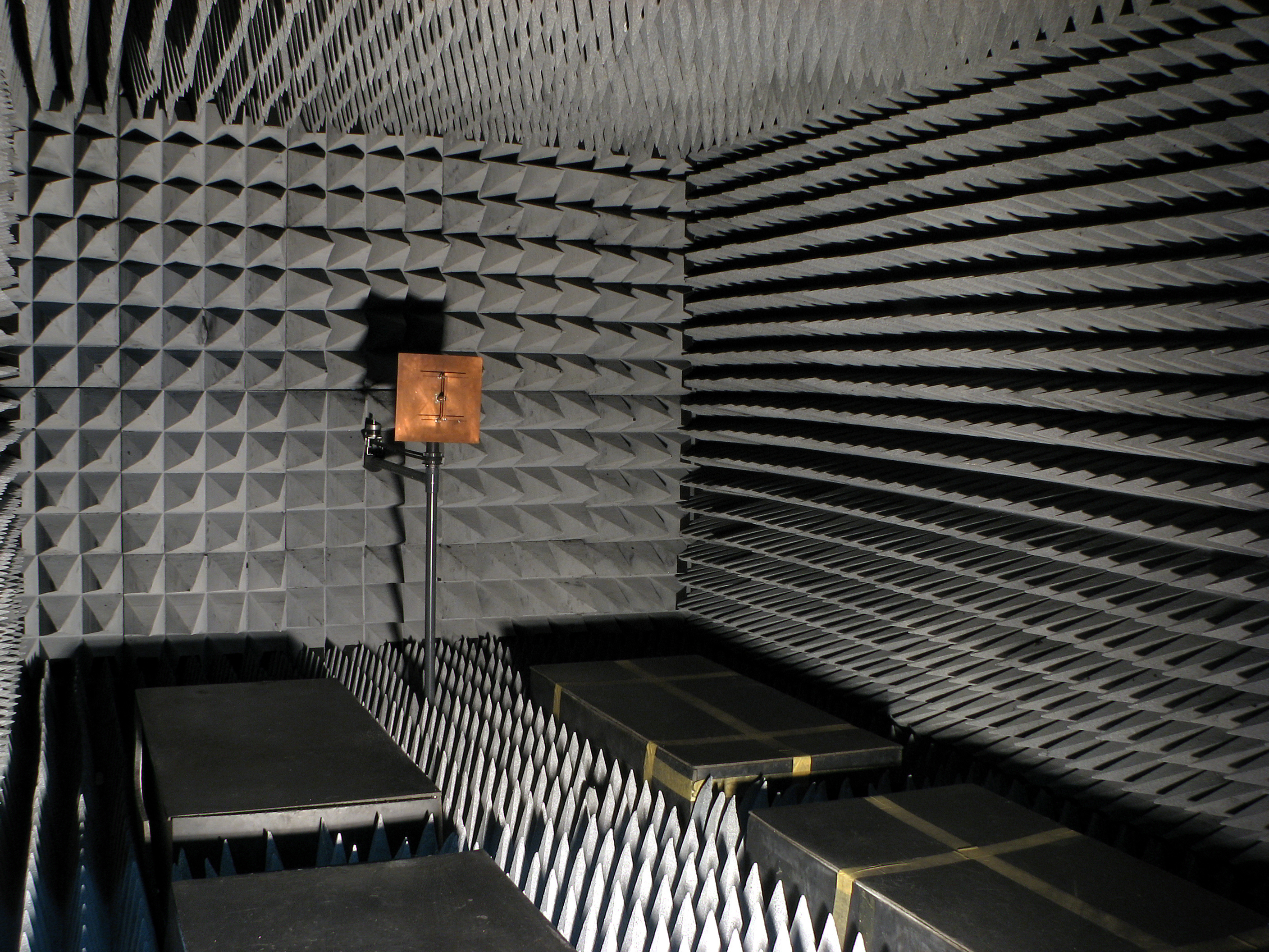 An RF anechoic chamber (source: Wikipedia)
An Anechoic Chamber is a shielded room lined with radio-frequency (RF) absorbing material on all sides, designed to simulate a free-space environment (like outer space, with no reflections).
Used For
- Radiated Emission Testing: Measure how much RF your product emits.
- Radiated Immunity Testing: Expose your product to controlled RF fields and see if it malfunctions.
Features
- Fully enclosed and shielded from external RF noise.
- RF absorbers prevent internal reflections (ensures accurate measurement).
- Controlled environment (temperature, humidity, no wind).
Pros
- Extremely accurate.
- Immune to external interference.
- Can test both large and small devices.
- Works across a wide frequency range (typically 30 MHz – 18 GHz or higher).
Cons
- Very expensive to build and maintain.
- Requires space and special infrastructure.
- Needs regular calibration and maintenance.
GTEM Cell (Gigahertz Transverse Electromagnetic Cell)
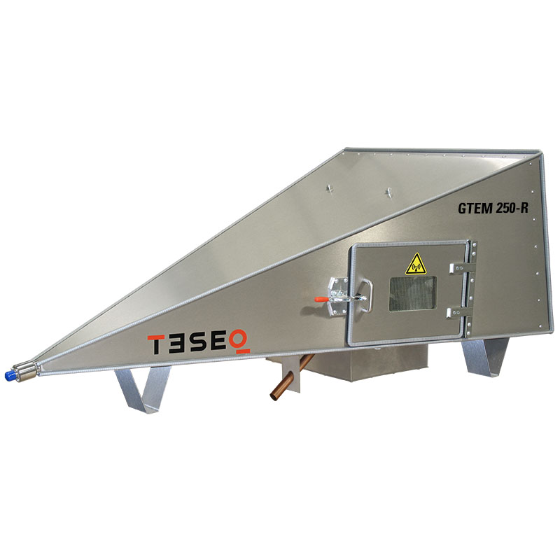 GTEM 250 (Source: https://www.ametek-cts.com)
A GTEM Cell is a compact, tapered metal enclosure that creates a TEM (Transverse Electromagnetic) field, simulating a plane wave environment inside a shielded box.
Used For
- Radiated Emission (pre-compliance, R&D)
- Radiated Immunity testing (up to ~1 GHz or 2 GHz for advanced models)
Features
- Coaxial input feeds RF signal into the tapered chamber.
- EUT sits on an internal platform.
- Compact alternative to large chambers.
Pros
- Small footprint — fits on a lab table.
- Faster and cheaper than anechoic chamber.
- Shielded, so no external RF leaks.
Cons
- Field uniformity isn’t perfect — less accurate than anechoic chambers.
- Limited size — only works for small DUTs (development boards, wearables, small devices).
- Limited frequency range (<2 GHz usually).
Open Area Test Site (OATS)
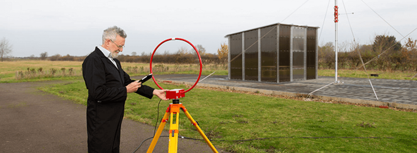 Open Area Test Site (OATS) (Source: https://apctech.com) An Open Area Test Site is an outdoor testing environment with a large metal ground plane and no nearby reflecting structures. It’s the traditional method for EMI radiated emission testing.
Used For
Radiated Emission Testing, mainly for formal compliance (e.g., FCC Part 15).
Features
- Outdoor setting.
- Standardized test distance (3m, 10m).
- Uses calibrated antennas and measurement equipment.
Pros
- Very accurate in ideal conditions.
- Official method accepted by regulatory bodies (FCC, CISPR).
- No chamber cost.
Cons
- Weather-dependent (rain, wind, temperature).
- Ambient RF noise can ruin measurements.
- Requires large open land and strict layout rules (vegetation, buildings, power lines must be far away).
- Time-consuming to set up.
Summary: EMI/EMC Test Environments
| Environment | Accuracy | Portability | Cost | EUT Size | Frequency Range | Best For |
|---|---|---|---|---|---|---|
| Anechoic Chamber | ⭐⭐⭐⭐ | ❌ | 💰💰💰💰💰 | Medium to Large | Up to 18 GHz+ | Final testing, certification labs |
| GTEM Cell | ⭐⭐⭐ | ✅ | 💰💰💰 | Small | Up to ~1–2 GHz | Pre-compliance, R&D |
| Open Area Site | ⭐⭐⭐⭐ | ❌ | 💰💰 | Medium to Large | 30 MHz – 1 GHz | Formal radiated emission testing |
Radiated emission
 The radiated emission test procedure using a GTEM cell, in accordance with 47 CFR §15.109, involves placing the equipment under test (EUT) inside the GTEM cell on a non-conductive support and operating it in a typical configuration with all necessary peripherals connected. The GTEM cell, which simulates far-field electromagnetic conditions, is connected to a spectrum analyzer or EMI receiver to measure emissions across the frequency range of 30 MHz to 1 GHz or higher. The test setup must be calibrated to correlate measurements to standard distances (3 meters for Class B and 10 meters for Class A devices) using correction factors. Emissions are measured using quasi-peak detectors, and the EUT may be repositioned to capture worst-case scenarios. The FCC limits for Class B devices range from 100 µV/m to 500 µV/m depending on frequency, while Class A limits range from 90 µV/m to 300 µV/m. Compliance is determined by comparing measured emissions against these limits, and any exceedances require mitigation through shielding, filtering, or design adjustments.
| Frequency Range | Class A Limit (µV/m at 10 m) | Class A Limit (dBµV/m) | Class B Limit (µV/m at 3 m) | Class B Limit (dBµV/m) |
|---|---|---|---|---|
| 30 – 88 MHz | 90 µV/m | 39.1 dBµV/m | 100 µV/m | 40.0 dBµV/m |
| 88 – 216 MHz | 150 µV/m | 43.5 dBµV/m | 150 µV/m | 43.5 dBµV/m |
| 216 – 960 MHz | 210 µV/m | 46.4 dBµV/m | 200 µV/m | 46.0 dBµV/m |
| Above 960 MHz | 300 µV/m | 49.5 dBµV/m | 500 µV/m | 54.0 dBµV/m |
Class A = Industrial/Commercial (measured at 10 m).
Class B = Residential (measured at 3 m, stricter limits).
Limits are expressed both in µV/m and dBµV/m.
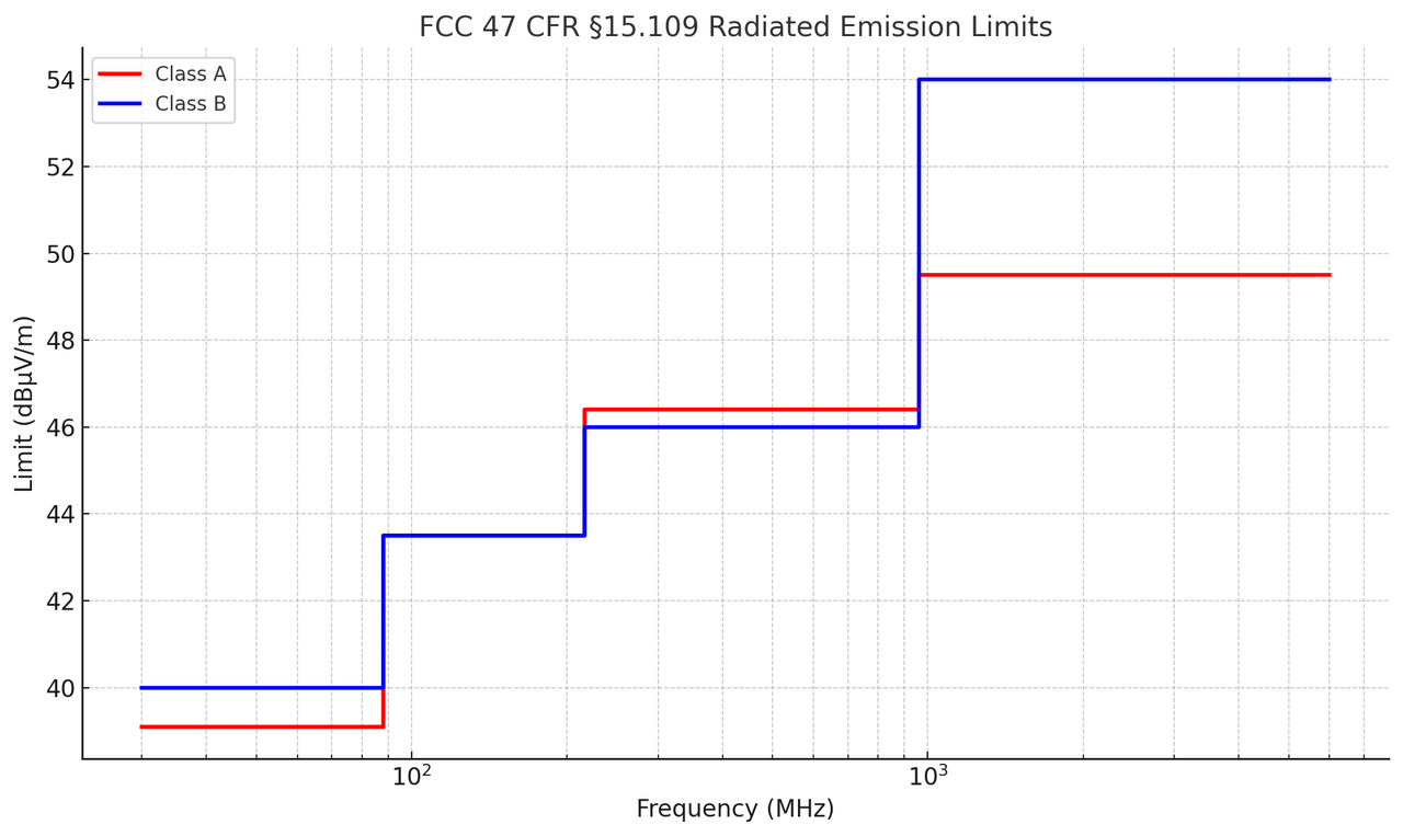 Image courtesy: ChatGPT
Red = Class A (Industrial/Commercial, 10 m)
Blue = Class B? (Residential, 3 m, stricter limits)
You can clearly see that Class B limits are tighter, especially above 960 MHz, where Class B is much stricter (54 dBµV/m vs 49.5 dBµV/m).
Radiated immunity

The IEC 61000-4-3 standard defines the procedure for testing the immunity of electrical and electronic equipment to radiated radio-frequency electromagnetic fields in the frequency range of 80 MHz to 6 GHz (or higher, depending on the product standard). The test is conducted in a semi-anechoic chamber (SAC) or GTEM cell, using a calibrated setup to ensure a uniform field area (UFA). The equipment under test (EUT) is placed on a non-conductive table 0.8 m above the ground plane, and exposed to an RF field generated by a signal generator, RF amplifier, and antenna. The field is typically amplitude modulated (AM) at 80% depth with a 1 kHz sine wave to simulate real-world disturbances
Before testing, the chamber is calibrated without the EUT using a field probe to measure field uniformity across 16 points in a 1.5 m × 1.5 m area. Calibration ensures that the forward power applied to the antenna produces the required field strength (e.g., 3 V/m, 10 V/m, or 18 V/m). During testing, the EUT is rotated and tested with both horizontal and vertical antenna polarizations, and the antenna is placed at a 3-meter distance from the EUT unless otherwise specified. The EUT must operate normally and show no signs of degradation or malfunction during exposure. Any susceptibility or failure is recorded, and the test may be repeated with different antenna positions to ensure full coverage.
| Frequency Range | Test Level 1 | Test Level 2 | Test Level 3 | Test Level 4 | Special |
|---|---|---|---|---|---|
| 80 MHz – 6 GHz | 1 V/m | 3 V/m | 10 V/m | 30 V/m | up to 200 V/m (military/automotive) |
| Modulation | 1 kHz sine, 80% AM | 1 kHz sine, 80% AM | 1 kHz sine, 80% AM | 1 kHz sine, 80% AM | Pulse modulation possible |
| Step Size | ≤1 % of current frequency | ≤1 % | ≤1 % | ≤1 % | ≤1 % |
| Dwell Time | ≥0.5 s per frequency | ≥0.5 s | ≥0.5 s | ≥0.5 s | ≥0.5 s |
Conducted emission

The conducted emission test under 47 CFR §15.107 is designed to measure the radio frequency voltage that is conducted back onto the AC power lines by digital devices operating within the frequency range of 150 kHz to 30 MHz. The test is performed using a Line Impedance Stabilization Network (LISN) rated at 50 µH/50 ohms, which isolates the Equipment under test (EUT) from the power source and provides a measurement point for conducted emissions. Measurements are taken between each power line and ground at the power terminal of the EUT. The limits vary depending on whether the device is classified as Class A or Class B. For Class B devices, the quasi-peak limit ranges from 66 to 60 dBµV, and the average limit from 56 to 50 dBµV, depending on the frequency band. For Class A devices, the quasi-peak limit is 79 dBµV from 0.15–0.5 MHz and 73 dBµV from 0.5–30 MHz, with corresponding average limits of 66 and 60 dBµV
| Frequency Range | Class A (QP) | Class A (Avg) | Class B (QP) | Class B (Avg) |
|---|---|---|---|---|
| 150 kHz – 500 kHz | 79 dBµV | 66 dBµV | 66 → 56 dBµV* | 56 → 46 dBµV* |
| 500 kHz – 5 MHz | 73 dBµV | 60 dBµV | 56 dBµV | 46 dBµV |
| 5 MHz – 30 MHz | 73 dBµV | 60 dBµV | 60 dBµV | 50 dBµV |
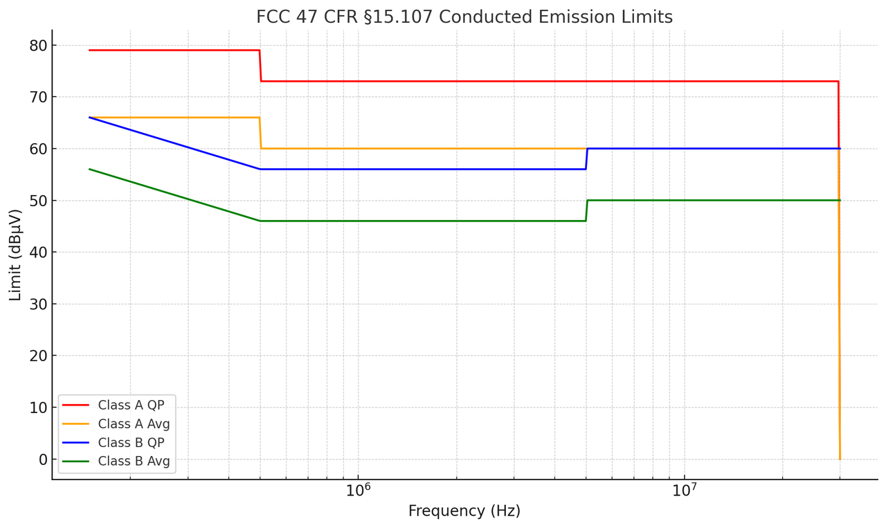 Image courtesy: ChatGPT
Red / Orange = Class A (QP & Avg)
Blue / Green = Class B (QP & Avg)
You can see Class B limits are stricter (lower) and have the sloped region between 150–500 kHz, while Class A limits are flat.
Conducted immunity

The IEC 61000-4-6 conducted immunity test evaluates the resistance of electronic equipment to RF disturbances in the 150 kHz to 80 MHz range. When using a current injection probe, the RF signal—modulated with a 1 kHz sine wave at 80% amplitude—is inductively coupled into cables connected to the equipment under test (EUT). The EUT is placed on a 0.1 m insulating support above a ground reference plane, with cables elevated 30 mm above the plane. The current probe is clamped around the cable under test, and the RF generator injects the signal at defined levels (typically 1 V, 3 V, and 10 V corresponding to 120, 130, and 140 dBµV). Decoupling networks are used on other cables to prevent unintended coupling. Each cable is tested individually while monitoring the EUT for performance degradation or functional disruptions. Environmental conditions such as temperature and humidity are recorded, and the EUT must continue to operate normally or recover automatically. Any anomalies are documented for compliance evaluation.
| Parameter | Value |
|---|---|
| Frequency range | 150 kHz – 80 MHz |
| Modulation | 1 kHz sine wave, 80% AM |
| Test voltage level | 1 V (120 dBµV) |
| Test voltage level | 3 V (130 dBµV) |
| Test voltage level | 10 V (140 dBµV) |
| Test voltage level (optional) | 30 V (150 dBµV) |
Reference
- https://www.tek.com/en/solutions/application/emi-emc-testing
- https://www.rohde-schwarz.com/us/solutions/electronics-testing/emc-testing/emc-testing_253441.html#gallery-14
- https://eepower.com/technical-articles/an-overview-of-conducted-emissions-part-1/#
- https://theemcshop.com/resources/
- https://www.intechopen.com/chapters/78512
- https://apctech.com/fully-anechoic-semi-anechoic-chambers-and-open-area-test-sites
- https://eepower.com/technical-articles/an-overview-of-conducted-emissions-part-1/
- https://www.emc-directory.com/community/what-is-immunity-testing-for-emc
- https://emcfastpass.com/emc-testing-beginners-guide/emc-immunity-testing/