Smartphone Mirror Lens Mod; How I Did It
Story
I have a SHARP Aquos R6 as a secondary backup smartphone in case of emergencies. I bought it very cheaply from a refurbished online store, it was a great deal for me, and the specs were also really good!
On December 20, 2024, I was riding my bike to my friend’s home. While on the way, I used this phone for navigation. Unfortunately, I met with an accident. I was riding peacefully at a speed of 45-50 km/h when suddenly a Swiggy delivery boy blindly overtook a vehicle very close to me. We collided, and it was a terrible situation.
Luckily, I was wearing my riding gear, as I always do, which protected me from physical injuries. However, my bike and phone weren’t as fortunate—both were severely damaged. 😢
After the accident, we went to the hospital for a check-up. A couple of months later, once everything was back to normal, I inspected my broken phone. Fortunately, there were no issues with its functionality. It only had minor scratches on the edges, but the back glass panel was shattered into a million pieces. 😢
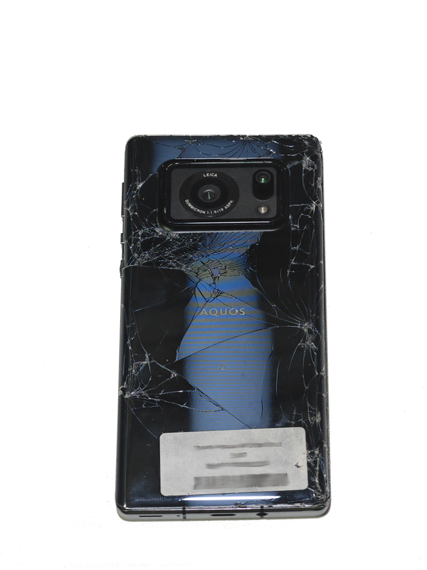 Broken phone
Inspiration
So, I’m very obsessed with smartphone photography. I got a couple of telephoto lenses, macro lenses, and wide-angle lenses.
I also tried to make a DoF adapter for my phone three years ago, but it didn’t go well. I bought all the required components for a Canon EF mount lens, but except for the lens, I mistakenly bought a Canon EF-M mount lens instead. At that time, I thought both were the same.
Anyway, I stuck with the project. There were so many challenges, but eventually, I gave up. You know, I tend to procrastinate, and over time, I completely forgot about this project.
Recently, I saw some videos about the Xiaomi 12S Ultra Concept:
I always wondered when something like this would be available in the market at an affordable price. But now, I think it’s time to make one myself at a very low cost.
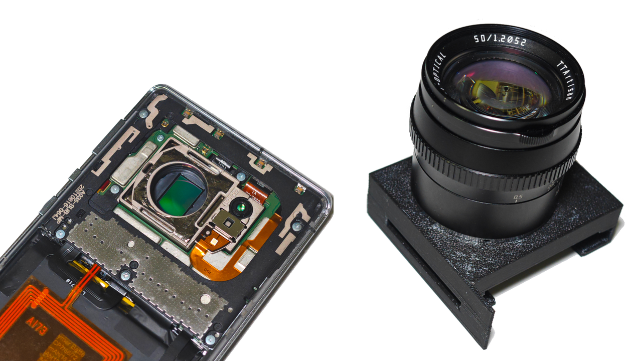
So in this project I’m using a Canon 50mm EF-M mount lens for my phone sensor!
Also, this YouTuber ModAndShoot inspired me to take action. I really appreciate his work and want to thank him! 🚀
Specification
Sharp Aquos R6 Camera Specifications
| Feature | Specification |
|---|---|
| Main Camera | 1-inch (1”) Leica sensor |
| Resolution | 20 MP (5,472 × 3,648 pixels) |
| Sensor Size | 1-inch (13.2mm × 8.8mm) |
| Aperture | f/1.9 (Wide) |
| Focal Length | 6.8mm (actual) / 19mm (35mm equivalent) |
| Lens | Leica Summicron 7-element lens |
| Image Stabilization | Electronic (EIS), No OIS |
| Autofocus | Laser AF + PDAF |
| Flash | LED Flash |
| Video Recording | 4K @ 30fps, 1080p @ 60fps |
| Front Camera | 12.6 MP, f/2.3 aperture |
| Additional Features | HDR10+, RAW support, Night mode |
Key Highlights
- Massive 1-inch sensor: One of the largest smartphone sensors for exceptional low-light performance and dynamic range.
- Leica-engineered lens: Delivers superior clarity, color accuracy, and professional-grade imaging.
- No Optical Image Stabilization (OIS): Relies on Electronic Image Stabilization (EIS) for video and photo stabilization.
- 8K video recording: Capture ultra-high-resolution videos at 30fps, with high-speed options like 4K @ 120fps and 1080p @ 240fps.
- Ultra-wide 19mm focal length (35mm equivalent): Perfect for landscapes, street photography, and capturing more in the frame.
- Night mode: Enhanced low-light photography for stunning night shots.
- RAW support: Allows for professional post-processing and editing flexibility.
- HDR10+: Ensures vibrant colors and high contrast in photos and videos.
TTArtisan 50mm f/1.2 Lens (Canon EF-M Mount) - Specifications
| Specification | Details |
|---|---|
| Focal Length | 50mm |
| Aperture Range | f/1.2 - f/16 |
| Lens Mount | Canon EF-M |
| Format Compatibility | APS-C |
| Angle of View | Approximately 31.7° (on APS-C sensors) |
| Optical Construction | 6 elements in 5 groups |
| Aperture Blades | 10 (for smoother bokeh) |
| Minimum Focus Distance | 0.5m (50cm) |
| Filter Thread Size | 52mm |
| Manual Focus | Yes |
| Autofocus | No |
| Image Stabilization | No |
| Dimensions | Approximately 56mm (diameter) x 55mm (length) |
| Weight | Approximately 300g |
| Build Material | Metal construction |
| Coating | Multi-layer coating to reduce flare and ghosting |
| Compatibility | Designed for Canon EF-M mount cameras (e.g., EOS M series) |
Technical part you must know!
About Actual Focal Length:
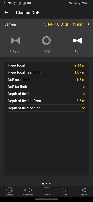 Screenshot from PhotoPills
- The actual focal length of the Sharp Aquos R6 is 6.8 mm, which refers to the physical distance between the lens and the sensor when focused at infinity.
- Actual focal length is important for determining the field of view. A 6.8 mm lens captures a wider scene compared to longer focal lengths.
- In smartphones with smaller sensors, the field of view may seem similar to that of a longer lens on a full-frame camera, which is why the 19mm (35mm equivalent) is often mentioned.
- While 6.8 mm is the real focal length, the equivalent focal length on a larger sensor is 19mm, providing an idea of how the lens compares to those on traditional cameras.
Flange Distance Explained
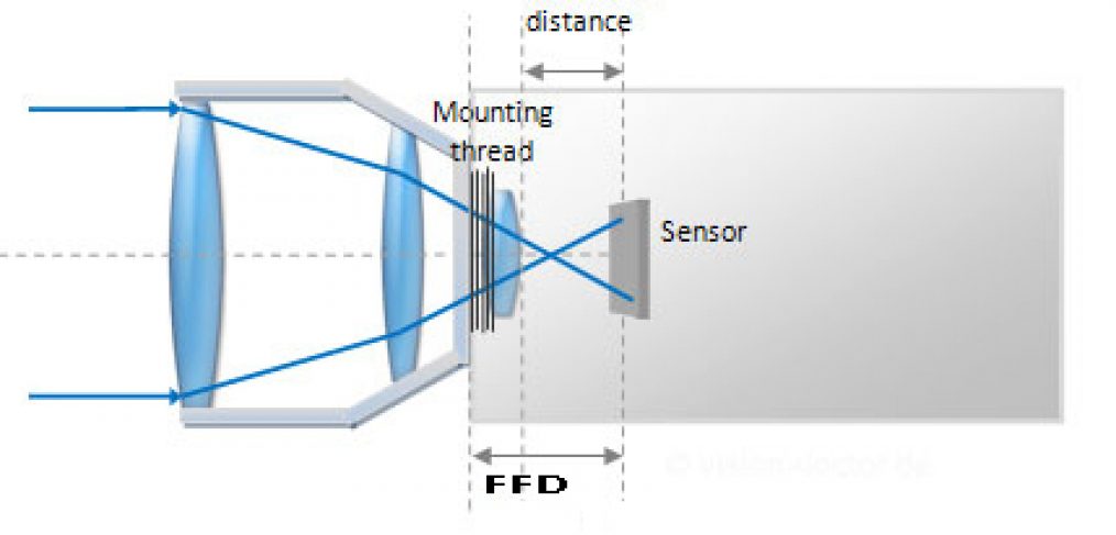 FFD Representation
The flange focal distance (FFD), also called flange-to-film distance, is the distance between the mounting flange of the camera lens mount and the image sensor plane. It’s a crucial measurement to ensure lenses focus correctly on the camera’s sensor.
Why Flange Distance Matters:
- Lens Compatibility – The FFD determines if a lens can be adapted to a camera body.
- Lenses with longer FFDs can be adapted to cameras with shorter FFDs using simple mechanical adapters.
Precision – Even small errors in the FFD can cause significant focus issues, which is why cameras are carefully calibrated to ensure accurate FFD.
- Film vs. Digital –
- In film cameras, the FFD is measured to the film plane.
- In digital cameras, it’s measured to the image sensor plane.
- This difference is key when adapting lenses across systems.
Flange Distance Table
A comparison of popular camera systems and their flange distances.
| Camera System | Flange Distance | Type | Format |
|---|---|---|---|
| Canon EF (Full-frame) | 44mm | DSLR | Full-frame |
| Canon EF-M (Mirrorless) | 18mm | Mirrorless | APS-C |
| Nikon F (Full-frame) | 46.5mm | DSLR | Full-frame |
| Micro Four Thirds (MFT) | 19.25mm | Mirrorless | Micro Four Thirds |
| Sony E (Mirrorless) | 18mm | Mirrorless | APS-C / Full-frame |
| Leica M (Rangefinder) | 27.8mm | Rangefinder | Full-frame |
| Pentax K | 45.46mm | DSLR | APS-C / Full-frame |
| Fujifilm X | 17.7mm | Mirrorless | APS-C |
| L-mount (Leica SL, Panasonic, Sigma) | 20mm | Mirrorless | Full-frame |
| C-mount | 17.526mm | CCTV | Small sensor |
Zoom Factor Calculation for a 1-Inch Sensor
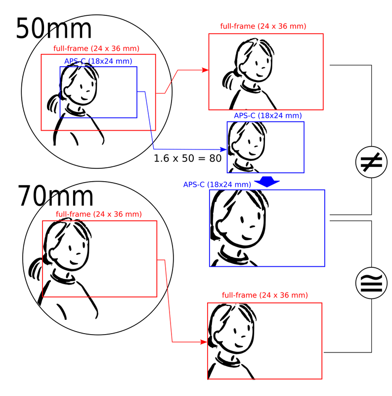 image courtesy:https://en.wikipedia.org/wiki/35_mm_equivalent_focal_length
When switching from a 6.8mm focal length lens to a 50mm focal length lens on a 1-inch sensor with a 4:3 aspect ratio, the zoom factor can be calculated as follows:
Step 1: Understand the Crop Factor
The 1-inch sensor has a crop factor of approximately 2.7x. This means the effective focal length of any lens mounted on this sensor will be multiplied by 2.7 to get its 35mm equivalent focal length.
Step 2: Calculate the 35mm Equivalent Focal Lengths
- For the 6.8mm lens:
- The 35mm equivalent focal length is already given as 19mm.
This is calculated as:
\(\begin{equation} \text{35mm Equivalent Focal Length} = \text{Actual Focal Length} \times \text{Crop Factor} \label{eq:35mm_equiv} \end{equation}\) \(\begin{equation} 19\, \text{mm} = 6.8\, \text{mm} \times 2.7 \label{eq:6.8mm_calc} \end{equation}\)
- For the 50mm lens:
The 35mm equivalent focal length is:
\[\begin{equation} \text{35mm Equivalent Focal Length} = 50\, \text{mm} \times 2.7 = 135\, \text{mm} \label{eq:50mm_calc} \end{equation}\]
Step 3: Calculate the Zoom Factor
The zoom factor is the ratio of the new focal length (50mm) to the original focal length (6.8mm). This tells you how much “closer” the subject will appear when using the 50mm lens compared to the 6.8mm lens.
\[\begin{equation} \text{Zoom Factor} = \frac{\text{New Focal Length}}{\text{Original Focal Length}} \label{eq:zoom_factor} \end{equation}\] \[\begin{equation} \text{Zoom Factor} = \frac{50\, \text{mm}}{6.8\, \text{mm}} \approx 7.35 \label{eq:zoom_calc} \end{equation}\]Step 4: Interpretation
- A zoom factor of 7.35x means that the 50mm lens will make the subject appear 7.35 times closer compared to the 6.8mm lens.
- In terms of 35mm equivalent focal lengths, the field of view changes from 19mm (wide-angle) to 135mm (telephoto).
Summary
- Original Lens: 6.8mm (19mm equivalent)
- New Lens: 50mm (135mm equivalent)
- Zoom Factor: \(\begin{equation} \frac{50}{6.8} \approx 7.35x \label{eq:zoom_summary} \end{equation}\)
This means the 50mm lens provides approximately 7.35x zoom compared to the 6.8mm lens on a 1-inch sensor.
Time for the Build
Now that you understand the basics of focal length, flange distance, and zoom factor, let’s dive into the build process. I’ll walk you through my journey of designing and prototyping, including the challenges I faced and how I overcame them.
Choosing the Right CAD Software
For this project, I’m using FreeCAD. As the name suggests, it’s free and open-source, and it’s available on Windows, Mac, and Linux 🐧. This made it an easy choice for me. I’ve never used any other CAD software for my mechanical projects, so I can’t compare it to other tools in the market. However, I find FreeCAD very capable and comfortable to work with, and it meets all my needs.
From Design to Reality: 3D Printing
Once the design was ready, I needed to bring it to life. For this, I used my Bambu Lab P1S 3D printer and printed the parts using black ABS material. ABS is strong, durable, and perfect for functional prototypes.
First Prototype: Lessons Learned
My first prototype didn’t turn out as expected. As someone new to mechanical CAD software, I faced several challenges. Here’s a breakdown of what went wrong and how I improved in the next iteration.
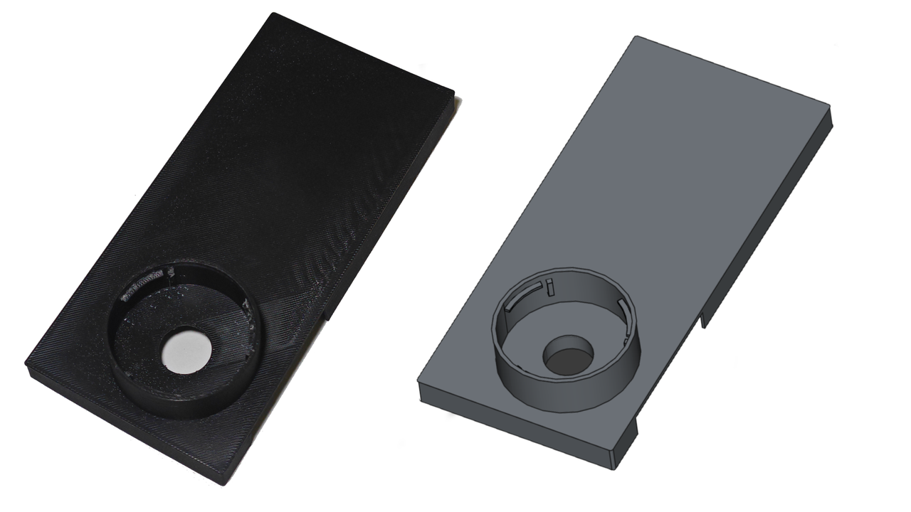 First Prototype
Problems I Faced
- Flange Distance Miscalculation:
- I misunderstood the flange distance initially. Even a 1mm difference can significantly impact the focus, and I couldn’t achieve infinity focus. This highlighted the importance of getting the technical details right.
- Measurement Errors:
- I used my trusty vernier calipers to measure the lens, flange distance, and phone dimensions. However, I didn’t account for tolerances, which made the phone cover and lens mount difficult to fit.
- Structural Weakness:
- The lens mount and phone case walls were only 2mm thick. After mounting the lens, the case started breaking apart due to the stress.
Changes for the Next Revision
- Improve the flange distance calculation.
- Add tolerances for better mounting of the lens.
- Optimize material usage to reduce waste.
- Increase the thickness of the lens mounting area for better durability.
Second Prototype: Progress and New Challenges
With the lessons from the first prototype, I made some improvements. However, new challenges emerged.
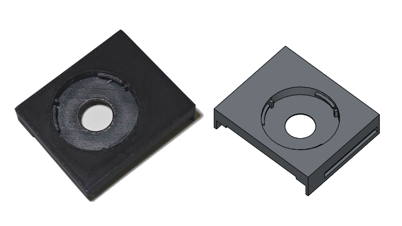 Second Prototype
Problems I Faced
- Weak Walls:
- I added slits for the power and volume rocker buttons, but this weakened the walls, causing them to break apart.
- Flange Distance Still Off:
- The flange distance was slightly better than the first prototype but still not perfect.
Changes for the Next Revision
- Strengthen the weak areas around the button slits.
- Fine-tune the flange distance for better focus.
Third Prototype: Almost There
The third prototype was a significant improvement, but there was still room for refinement.
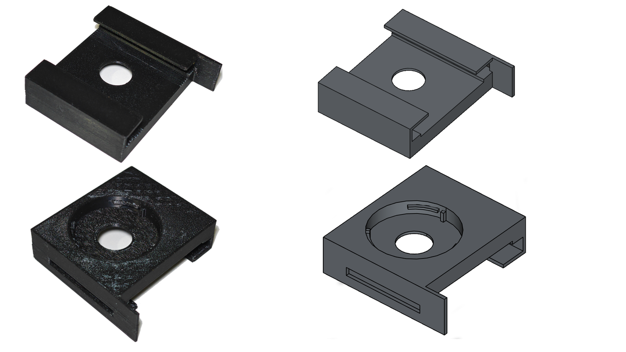 Third Prototype
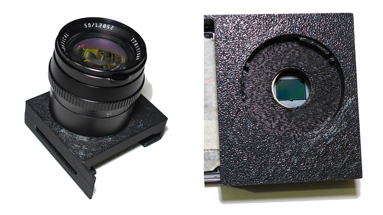 Sensor and Lens
Problems I Faced
- The flange distance needed to be increased by 0.5mm to achieve proper infinity focus. While it was close, it wasn’t perfect.
Changes for the Next Revision
- With more confidence in the design, I plan to create a full-body case for the phone.
- Add a Bluetooth shutter button for better control.
- Include a provision for an IR cut filter to block unwanted infrared light.
Learning from Mistakes
Like Tony Stark, I believe in learning from mistakes. I used to be a perfectionist, which often left me stuck in the middle of projects or prevented me from even starting them. But now, I embrace the iterative process of prototyping and improving. Each failure teaches me something new, and that’s how I grow.
What’s Next?
- Finalize the full-body case design.
- Integrate the Bluetooth shutter button and IR cut filter.
- Share the final design and results with the community.
Key Takeaways
- Flange distance is critical for achieving proper focus.
- Tolerances are essential for ensuring parts fit together seamlessly.
- Structural strength must be balanced with design aesthetics.
- Iterative prototyping is the key to success.
Sample Photos
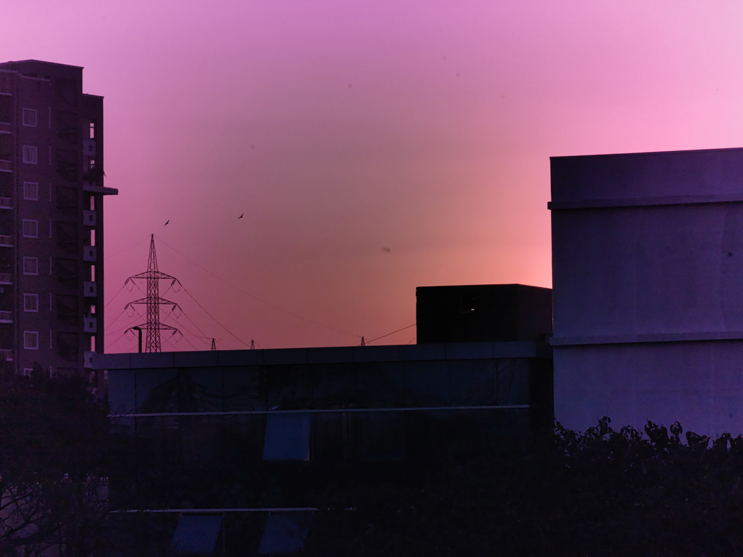
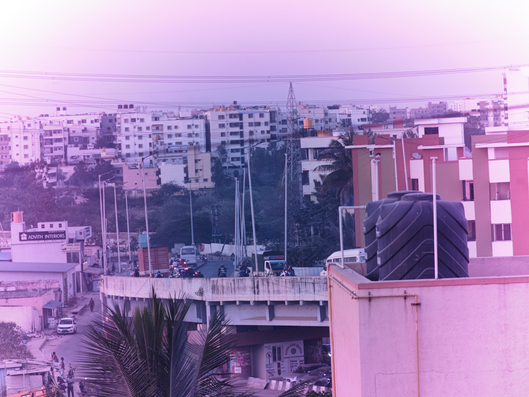
I took some photos with this lens. Please take a look and enjoy the results! You might notice a reddish-pink tint in some of the photos. This is because there’s no IR cut filter installed yet. I’ll address this in the next revision.
 Portrait
 Portrait
 Portrait
 Portrait
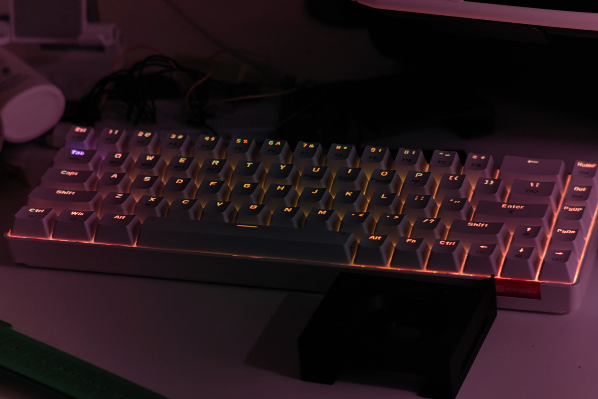
 Low light
 Low light
 Low light
 Low light
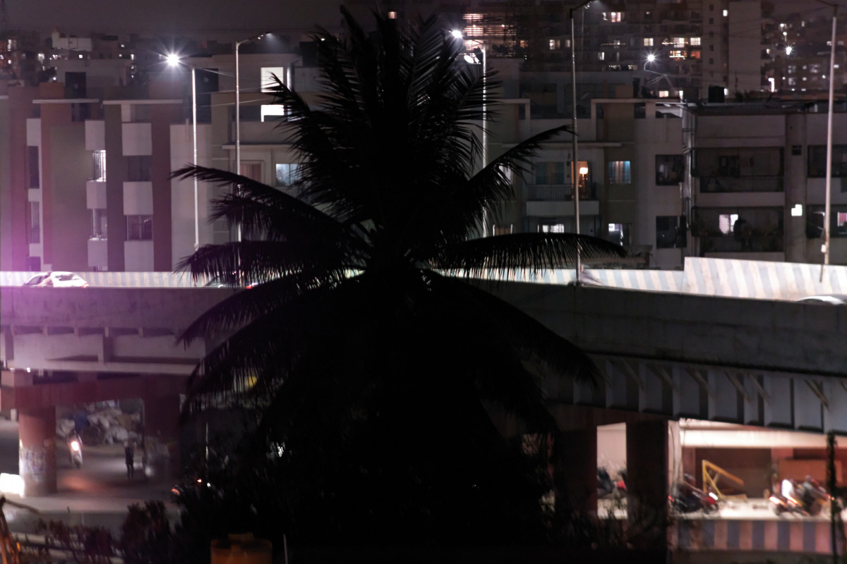 Low light
Observations:
- The lens captures sharp details and produces a beautiful bokeh effect.
- The reddish-pink tint is caused by infrared (IR) light interference, which will be resolved with an IR cut filter in the next version.
This iterative process has been incredibly rewarding, and I’m excited to see the final product come to life. Stay tuned for more updates! 😊